Best Wireless AP for UK Businesses: How to Choose in 2026
Compare the best wireless AP options for UK businesses by throughput, radios, security and management, with a vendor-neutral testing method.
Distance for WiFi depends on band, walls and access point placement, not one radius. See UK range benchmarks, a link budget method and practical fixes.
Stop asking how far a router reaches and expecting one number to survive contact with a real building. That's the most popular advice about distance for WiFi, and it's the advice that creates dead bedrooms, stalling payment terminals and hotel rooms where the network name is visible but a video call won't hold. A device can detect a beacon long after throughput, latency and roaming have become unusable.
I would plan every site the other way round. Decide what each room needs, work out what the walls and floors will take away, then place access points so clients stay above a usable threshold with margin to spare. Newer WiFi doesn't change that logic. It mainly adds capacity near the access point, which is useful, but it isn't reach.
There's no single WiFi range you can quote with certainty. The useful figure is usable distance, meaning the distance at which a client still gets reliable throughput at roughly -70 dBm or stronger, not the furthest point where it can see the network name.
| Environment | 2.4 GHz | 5 GHz | 6 GHz |
|---|---|---|---|
| Open-plan office, line of sight | 35-45 m | 25-35 m | 15-25 m |
| Plasterboard walls, one or two rooms | 25-35 m | 15-25 m | 10-15 m |
| Brick or block walls | 15-25 m | 10-15 m | 5-10 m |
| Concrete floor, next storey up | 10-15 m | 5-10 m | 3-5 m, plan a separate access point |
Treat these as starting points for access point spacing, then prove them on site. A foil-backed partition, a lift shaft or a crowded neighbouring network can make the optimistic end of any row irrelevant.
Start with the environment closest to the actual path, not the floor area. A 20 metre path across an open office and a 20 metre path through two brick walls and a bathroom pod are different jobs, even though the tape measure says they're the same.
Then use the band the client will really use. Laptops, phones, scanners, door locks and IoT sensors don't all have the same radios, antennas or band support. If you're designing for a scanner that only works well on 2.4 GHz, the 6 GHz column doesn't help you.
Plan for the room where the device must work, at the height and position where a person will use it, then check the result in the field.
Ofcom's spectrum access modelling for 5 GHz WiFi identifies 2.4 GHz as the UK's most commonly used Wi-Fi band, while noting that 5 GHz has shorter transmission range despite offering substantially more spectrum and wider channels. It also puts the available spectrum at 83 MHz at 2.4 GHz and 585 MHz at 5 GHz, which is why I wouldn't treat 2.4 GHz as a capacity band even though it travels further.
The same modelling applies approximately 12 dB of building-penetration attenuation when an indoor access point communicates with an outdoor receiver. Don't lift that figure and use it as a generic indoor wall loss. It shows that a building boundary matters, but your indoor loss depends on the actual construction in the path.
Use 2.4 GHz for coverage-critical or obstructed areas, such as legacy devices, awkward corners and low-rate IoT. Use 5 GHz as the main capacity layer in most offices, hotels and student accommodation. Add 6 GHz where clients support it and you can place cells densely enough to keep them close. That last point matters more than the band labels suggest: newer generations add capacity near the access point, so a 6 GHz deployment only pays off when the devices stay inside its shorter usable radius.
Even a favourable indoor test shouldn't become a design promise. Reinforced concrete, metal structures, floors and poor access point placement can cut usable distance sharply on the next site.
The same room by room thinking applies when a building itself is temporary or assembled in modules. If you're planning connectivity for distributed teams in that kind of space, it's worth seeing how others explore modular workspaces for remote teams before you assume a standard office layout. Partition material and module joins still decide where access points belong.
For dense commercial sites, I would rather install additional access points at lower transmit power than stretch one cell until its edge becomes unreliable. Smaller cells give you cleaner roaming, more airtime per client and fewer arguments about whether a weak connection counts as coverage.
WiFi works like a torch beam in fog: distance dims it steadily, and every wall, floor and coated pane of glass takes another share before the signal reaches the client. You don't fix fog by quoting the torch's maximum range.
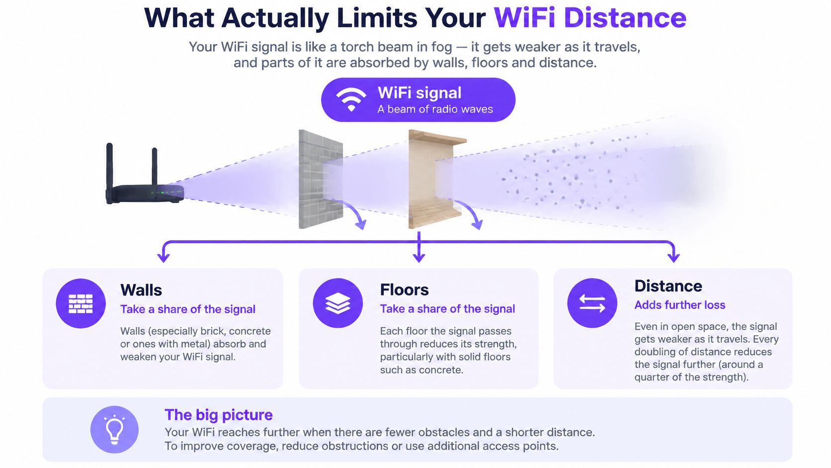
In open space, every doubling of distance costs about 6 dB. A 3 dB loss roughly halves received power, so a few obstacles quickly turn a healthy signal into a marginal one. Clients then drop to lower data rates, retry more often and consume more airtime for the same traffic.
| Factor | Typical loss | Effect on usable range |
|---|---|---|
| Each doubling of distance in open space | about 6 dB | Leaves roughly a quarter of the original received power |
| Plasterboard or stud wall | 3-5 dB | Cuts usable range noticeably per wall |
| Brick or block wall | 5-10 dB | Often limits a room to one or two walls |
| Reinforced concrete floor | 15-20 dB | Usually needs its own access point |
| Fire door or metal-framed door | 5-10 dB | Can isolate a corridor or stairwell |
| Low-emissivity or metal-coated glass | 3-10 dB | Weakens coverage from outside or across atriums |
| Building penetration at higher frequencies (measured at 7.6 and 13.6 GHz) | Severe attenuation through the structure | Shows how sharply a building cuts signal at frequencies above the Wi-Fi bands |
| Interference and noise | Raises the noise floor rather than subtracting a fixed dB value | Lowers signal-to-noise ratio even when signal level is fair |
Treat the higher-frequency penetration row as a direction of travel rather than a design input. Attenuation climbs as frequency rises, and a structure that passes 2.4 GHz tolerably can still gut anything above it. For a 2.4 GHz or 5 GHz design, use material losses that match the band and construction in the path, then walk the building room by room to confirm them.
A client needs a clean enough signal-to-noise ratio, and a strong reading in dBm alone tells you nothing about whether frames decode reliably. Neighbouring networks, Bluetooth, cordless devices, microwave ovens and your own overlapping cells all raise contention or noise. The access point can look loud while the client still can't get a usable connection.
That's why turning power up often disappoints. Louder cells overlap more, clients cling to distant access points, and the return path from a battery-powered phone stays weak regardless of what the access point transmits. UK rules also cap transmit power as EIRP, and for 2.4 GHz you should check against 100 mW (20 dBm) before raising power. Even where headroom exists, I wouldn't spend it before fixing placement and channel reuse.
802.11n, 802.11ac, 802.11ax (Wi-Fi 6) and 802.11be (Wi-Fi 7) improve scheduling, efficiency and capacity. That extra capability shows up close to the access point. Reinforced concrete still costs the same 15-20 dB, so newer standards extend what clients can do inside a well-served room rather than pushing coverage into rooms the signal can't reach. Higher bands generally attenuate more through walls, which means extra spectrum delivers speed near the cell while doing nothing for a space two floors away.
Ookla data reported by ISPreview put the UK shares at 43.4% Wi-Fi 6 and 3.8% Wi-Fi 7, while Wi-Fi 5 still represented 38.7% and Wi-Fi 4 14.1%. Your design therefore has to serve a mixed client estate, where the oldest device in a corridor sets a real constraint the newest phone in the sales meeting can't lift.
Distance is a per-room question answered in dB: frequency, materials, placement, interference and the client's own radio each take their share. The range figure on the box is marketing's problem, and I'd leave it there.
A quoted range is the lazy version of coverage planning. A link budget adds gains, subtracts losses and compares the remainder with the level a client needs, so the question becomes margin in each room rather than metres on a datasheet.
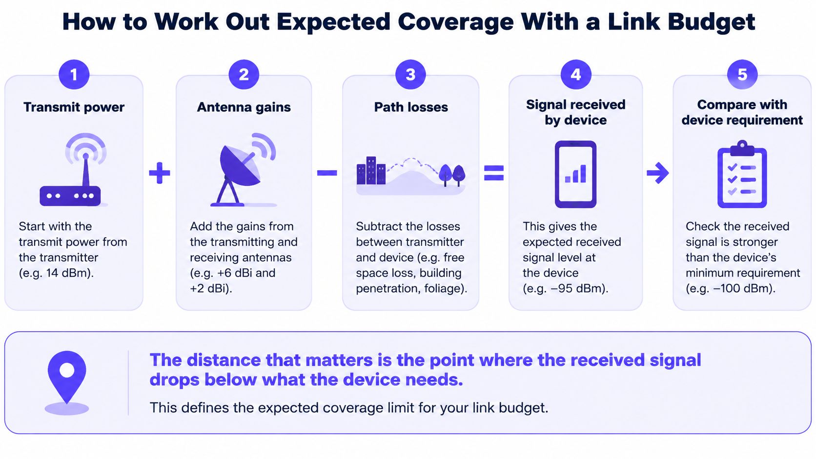
The UK Government guidance on Wi-Fi radio waves and health identifies the principal Wi-Fi operating bands as approximately 2.4 GHz, 5 GHz, and 6 GHz. Choose the band for the job first: higher frequencies can carry more traffic close to the access point, while lower ones usually reach farther through the same building. The budget then decides whether a particular seat, bed or scanner position closes.
Usable distance is the point where required signal strength, reliability and throughput still hold together. A beacon you can barely detect does not prove a room is covered, and a fast result beside the access point says little about the far corner behind a riser.
Take a hypothetical 2.4 GHz access point transmitting at 17 dBm with a 3 dBi antenna. That gives 20 dBm EIRP for the worked path. The client has a 0 dBi antenna and sits 20 metres away through one plasterboard wall.
Allow about 66 dB of free-space loss at 20 metres and 4 dB for the wall. The received level is 20 minus 66 minus 4, which gives -50 dBm. Subtract a 12 dB fade margin and you're planning around -62 dBm.
That's 8 dB above a -70 dBm general-data threshold, so the cell is usable with sensible headroom. Add a brick wall, move the client behind a metal cabinet or drop to a weaker handheld device, and that headroom disappears quickly.
Margin decides the result: A 20 metre path with positive margin is coverage. A 12 metre path with negative margin isn't, however close it looks on a plan.
Run the budget for the worst legitimate client position in each key room. Corners furthest from the door, beds against external walls, desks behind storage and seats beside lift cores are better test points than the centre of an empty room.
Also check the reverse direction. If the access point transmits much louder than the client can answer, you'll create a connection that looks present but stalls under traffic. Balanced power and smaller cells usually roam more cleanly than one loud access point trying to dominate a floor.
Treat the calculation as a starting estimate. Use it to place access points provisionally, then revise the losses where measured rooms disagree with the plan.
Hit the thresholds in the rooms that matter, or don't call the design finished. For voice and video, aim for -67 dBm or stronger. For general business data, aim for -70 dBm or stronger. In both cases, look for a signal-to-noise ratio of about 25 dB or more if you want stable throughput rather than a fragile association.
| Use case | Minimum signal | Signal-to-noise ratio |
|---|---|---|
| Voice and video | -67 dBm or stronger | about 25 dB or more |
| General business data | -70 dBm or stronger | about 25 dB or more |
Bring a laptop or phone running a proper analyser, a scaled floor plan and a list of the device types that will use the network. A browser speed test on your own flagship phone isn't a survey. If you need a practical starting point for tooling, this guide to choosing a WiFi analyzer application covers what to look for before you walk the site.
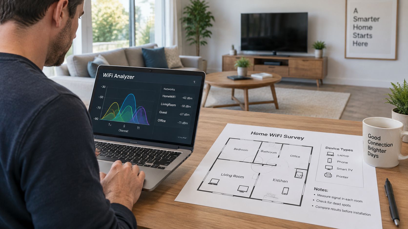
Stand in each room at desk height, bed height or scanner height, depending on the job. Test by the door and at the furthest usable corner, because readings can change materially across a few metres. Shut fire doors where they'll normally be shut, since an open door can hide a problem you'll inherit after handover.
Walk corridors slowly enough to observe roaming behaviour. Note where the client lets go of one access point, which one it joins next and whether traffic stalls during the transition. Include stairwells, lifts, basements, plant-adjacent areas and any room where staff stand to complete a task.
Produce a heat map where the tooling supports it, or a room by room table marked pass, marginal or fail. Marginal isn't a pass you can explain away. It's a warning that occupation, furniture or a neighbouring network can push the room over the edge.
I would adjust the link budget to match measured losses, then move or add access points based on that evidence. If a corridor access point can't serve the far side of a hotel bedroom through a bathroom pod, the answer is usually an in-room or closer access point, not more power in the corridor.
The survey decides where access points go. Keep the floor plan, readings, device types and test positions together so another engineer can repeat the walk and get comparable results after you make changes.
Start with backhaul, not product category. If you can cable it, you remove the weakest link from the design.
| Option | Best for | Main trade-off | Backhaul needed |
|---|---|---|---|
| Wired access point | Multi-room offices, hotels, student housing | Cabling cost and installation time | Ethernet cable |
| Mesh system | Homes and small sites with no cabling route | Wireless hops share airtime and lower throughput | Wireless or Ethernet |
| Range extender | One dead room that no access point can reach | Halved throughput and a second network name | Wireless |
| Wireless bridge | Outbuildings or a second building in line of sight | Clear line of sight and link rules to check | Wireless point to point |
| Directional antenna | Long narrow corridors or outdoor links | Narrow beam must be aimed carefully | Depends on access point |
For a multi-room commercial site, I'd choose wired access points wherever there's a practical cabling route. Each radio gets full wired backhaul, you control channel and power per cell, and roaming is designed rather than improvised. The cost is real, especially in occupied hotels or listed buildings, but so is the cost of revisiting a site that never had enough capacity.
Managed platforms can run across different hardware, so you don't have to let vendor lock-in decide the radio design. Purple, for example, operates as a hardware-agnostic overlay on existing access points for guest, staff and multi-tenant access. That's separate from RF design. Choose access point positions for coverage and capacity first.
Mesh suits homes and small sites where cabling is impractical and traffic is moderate. Nodes coordinate under one network name and can steer clients more sensibly than an isolated repeater. Place each node where it still has a strong link back towards the root, not inside the dead zone you're trying to rescue.
Every wireless hop shares airtime. One hop may be acceptable for browsing and streaming, but several hops through brick walls will eat throughput and add latency. If a node can take Ethernet backhaul later, that's an upgrade worth planning for.
An extender is a patch for one dead room. It listens and retransmits, which typically halves available throughput on that link and can leave clients attached to a weaker repeated signal. A separate network name makes the experience worse because devices don't always move when they should.
I wouldn't build a student block, clinic or hotel floor out of extenders. Use one only where the requirement is light, the room can't be reached by a proper access point and the customer understands the compromise.
A wireless bridge links buildings where digging or cabling isn't practical. It needs clear line of sight, careful alignment and a check of power, licensing and mounting rules before installation. Trees, new signage and construction can intrude into the path later, so document the route and keep it clear.
Directional antennas help in long corridors, warehouses and outdoor point-to-point paths because they concentrate energy where it's needed. They don't create energy from nowhere. Aim them badly and you'll create a strong strip of coverage with dead areas either side.
If you're comparing whole architectures rather than single products, these WiFi solutions for businesses set out the service models that sit on top of the radio layer. The decision rule stays simple. Cable commercial access points where you can, use mesh where you can't cable a small site, and reserve extenders for a single stubborn room.
The complaint usually sounds vague: a device connects, works for a while, then drops or stalls in one room. Resist replacing hardware first. Separate weak signal, poor signal-to-noise ratio, bad roaming and congestion, because each fault has a different fix and the wrong change can hide the cause for another week.
Hospitality makes the same coverage mistake expensive. Guests judge the connection in the room rather than the corridor heat map; the wider “work where you stay” expectation behind guides such as what Tulum offers remote workers is a useful reminder that the test point is the chair, desk or bed, never the doorway. Prove service at that position.
Most configuration fixes take one visit and a re-survey. Structural fixes take longer. Adding wired access points, opening ceilings or agreeing a new cabling run in an occupied building can take weeks to schedule, so identify that need early rather than spending three visits tuning a cell that is in the wrong place.
A fix is proven when the same room passes the agreed signal, signal-to-noise and traffic tests with the client's real devices, not when the bars improve.
Change one variable at a time where you can. Move an access point, retest. Narrow a channel, retest. Adjust a roaming threshold, then walk the route again. If you change power, channel, band steering and placement in one visit, you will know the result changed without knowing why.
Coverage drifts after handover. Tenants move furniture, neighbours install louder networks, a refit adds foil-backed insulation and firmware changes radio behaviour. If you only return when users complain, you'll always be diagnosing yesterday's problem with incomplete evidence.
Set alerts on thresholds rather than raw counts. Ten retries means little without context, but a sustained rise in retries, weak clients or noise on one radio tells you where to walk first. That's more useful than a dashboard full of green lights while a meeting room fails.
Understanding the wider device load also helps you forecast capacity. This overview of how many devices are connected to the internet is useful context when clients ask why last year's design now carries more phones, sensors and laptops per person. More devices don't reduce radio range directly, but they consume airtime and expose weak cell edges sooner.
Re-survey after any refit, new partition, tenant change or layout change. I'd also run a quick walk test each quarter in the rooms that matter most, using the same positions and device types as the original survey. Managed monitoring tools can collect these measures across several client sites, which helps an MSP spot patterns and evidence service levels before a support call sets the agenda.
Keep a handover pack in one place. Include the scaled floor plan, access point positions, transmit settings, channel plan, survey date, pass thresholds and the last room by room results. The next engineer should be able to compare today's readings with the signed-off baseline without reconstructing your decisions from email threads.
Don't sign off because every access point is online. Sign off because the site passes the tests you agreed before installation.
Hand over the floor plan, survey results, channel and power settings and monitoring plan together. A customer who only receives a list of installed access points can't tell whether their building still performs as designed in six months.
If a site fails any point, re-run the link budget with measured losses, move or add an access point and re-survey before sign-off. I would rather delay handover for one cable run than accept a marginal room and spend the next year explaining why a visible network isn't a usable one.
Purple helps MSPs, integrators and venue operators turn properly surveyed WiFi into managed guest, staff and multi-tenant services, with identity-based access and reporting layered over the access points already on site. If you're planning coverage room by room and want a hardware-agnostic way to run and evidence that service across client sites, visit Purple to explore the partner platform.
Join 80,000+ venues already running on Purple. No targets, no minimums, just bigger deals.